
Steam Pressure Valve Selection: U.S. KNKE Guide
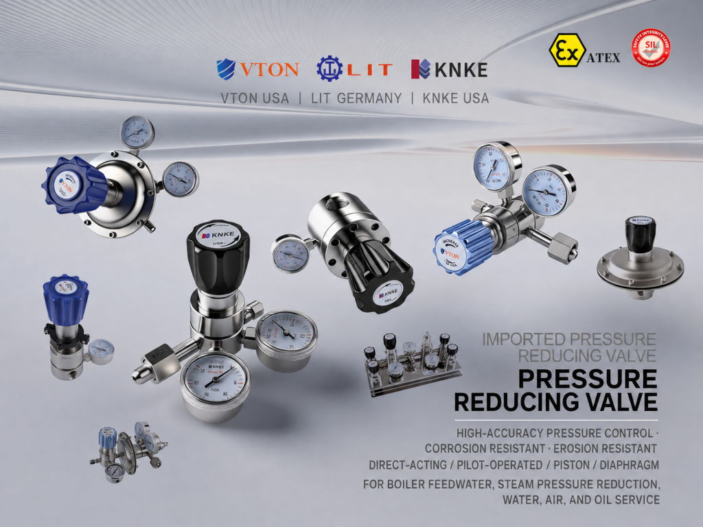
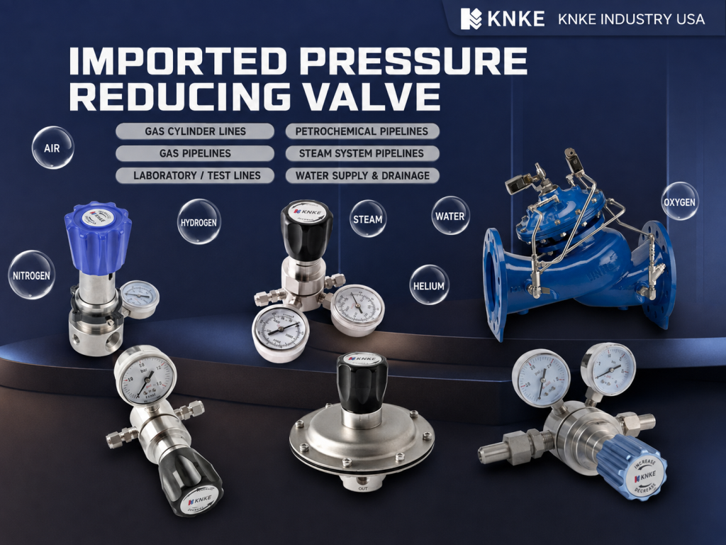
Imported Pressure Reducing Valve for Industrial Systems
An imported pressure reducing valve lowers high inlet pressure to the level required by downstream equipment. It also responds to changes in flow demand. This function helps steam, air, water, and process gas systems maintain a suitable outlet pressure.
Industrial plants often use one main pipeline to supply several machines. However, the main line may operate at a higher pressure than the equipment can handle. Direct supply may affect temperature control and increase the load on pipes and accessories.
A pressure reducing valve controls pressure through a disc, spring, diaphragm, piston, or pilot system. When downstream pressure changes, the valve adjusts its opening. Different designs suit different flow rates and pressure conditions.
U.S. KNKE supplies valves, flowmeters, pumps, actuators, and fluid control solutions. KNKE Industrial (Shenzhen) Co., Ltd. supports sales and service in the Asia-Pacific market. Its team assists users with valve selection, condition reviews, and technical documents.
Steam Pressure Reduction Case
A fine chemical plant plans to improve its reactor steam tracing system. The main steam line has a design pressure of about 1.6 MPa. However, the reactor jacket requires only 0.35–0.45 MPa.
The branch line carries about 1.2–1.8 t/h of steam. At an inlet pressure of 1.6 MPa and an outlet pressure of 0.45 MPa, the pressure ratio reaches about 3.6:1.
The initial plan uses a DN50 pilot-operated piston valve. The proposed pressure rating is PN25. Its outlet setting range covers 0.3–0.6 MPa.
These values support the early technical review. Engineers must still check the following data:
- Minimum and maximum steam flow;
- Steam temperature and condition;
- Normal and maximum inlet pressure;
- Allowed outlet pressure change;
- Pipeline size and flange standard.
The team should not select an imported pressure reducing valve by pipeline size alone. The actual flow and pressure drop determine the required valve capacity.
Imported Pressure Reducing Valve Structure
An imported pressure reducing valve must respond to pressure and flow changes. Temperature and medium properties also affect its structure. The main components perform different control functions.
Main Valve Assembly
The main assembly includes the body, disc, seat, and stem. These parts change the internal flow area. A wider opening allows more medium to pass through the valve.
Pressure-Sensing Assembly
A diaphragm or piston senses downstream pressure. Pressure changes move this part and create a mechanical response.
Pressure-Setting Assembly
A spring sets the required outlet pressure. Operators can adjust the spring within the stated pressure range.
Pilot Control Assembly
A pilot valve controls the opening of the main valve. This design suits systems with large changes in flow demand. It can provide stable control in variable-load steam lines.
Matching the Valve to Flow Demand
In the steam tracing example, the flow may change from 0.5 to 1.8 t/h. This equals a flow ratio of about 3.6:1. Several reactors may start or stop at different times, which changes steam demand.
A pilot-operated imported pressure reducing valve senses the outlet pressure. It then changes the main valve opening. This response makes the design suitable for the planned steam branch line.
Small systems may use a direct-acting valve instead. Common applications include instrument air, cleaning equipment, and low-flow water lines. Engineers should base the final choice on flow, pressure, and control needs.
Common Sizes and Pressure Ratings
Industrial pressure reducing valves often cover sizes from DN15 to DN300. Common pressure ratings include PN16, PN25, and PN40.
Some steam models can operate at temperatures near 200°C. The actual limit depends on the body material, seal type, and internal components. Users should check the product data before confirming a model.
Controlling a Large Pressure Drop
A large pressure drop may cause noise, vibration, and internal wear. For example, reducing pressure from 2.5 MPa to 0.2 MPa creates a ratio of 12.5:1.
One valve may not suit such a large reduction. Engineers can consider a two-stage system. Each valve then handles a smaller pressure difference.
Two-stage pressure reduction may also support steadier control at low outlet pressures. However, the system still needs correct pipe sizing, condensate drainage, and safety protection.
How to Select an Imported Pressure Reducing Valve
Selecting an imported pressure reducing valve requires more than checking the nominal pipe size. A DN50 pipeline may carry steam, compressed air, water, or process gas. Each medium has different flow properties.
U.S. KNKE reviews four main groups of data during selection.
1. Medium and Temperature
The medium affects the body and seal materials. A normal steam system may use a WCB carbon steel body with heat-resistant seals.
Corrosive media require a separate material review. Engineers may consider CF8M stainless steel or another compatible material. They should confirm chemical compatibility before selecting the final configuration.
2. Inlet and Outlet Pressure
Engineers need the normal, maximum, and minimum inlet pressures. They must also define the target outlet pressure and its allowed range.
For an inlet range of 1.2–1.6 MPa, the highest value supports the pressure rating check. The lowest value helps confirm whether the valve can still supply enough flow.
3. Maximum and Minimum Flow
An oversized valve may remain at a small opening. This condition can cause pressure changes and repeated disc movement.
An undersized valve creates another problem. It may fail to supply enough steam at full load. The selected valve should support both high demand and low-load operation.
4. Pipeline Connections
The flange standard must match the existing pipeline. Engineers also need to confirm the pressure rating, facing type, flow direction, and accessory ports.
An incorrect flange or facing type may delay installation. Clear technical documents can reduce this risk.
Standards and Product Checks
Technical standards help users review valve design and test requirements. ASME B16.34 covers pressure-temperature ratings, materials, dimensions, tests, and marking for certain industrial valves.
ISO 5208 provides test requirements for industrial metal valves. It covers pressure boundary checks and seat leakage tests.
The project team should confirm which standards apply to the selected imported pressure reducing valve. The valve structure and project rules will affect this decision.
A complete data sheet should include:
- Medium and operating temperature;
- Maximum and minimum inlet pressure;
- Required outlet pressure;
- Maximum, normal, and minimum flow;
- Nominal size and pressure rating;
- Flange standard and facing type;
- Body, trim, and seal materials;
- Required tests and documents.
A complete data sheet reduces repeated model changes. It also helps users check whether the valve matches the project.
Project and Delivery Coordination
Industrial users often consider control performance, product documents, delivery time, and after-sales support. Missing technical details can slow a project before production starts.
For example, a late flange change may require a new model review. An unclear outlet pressure range can cause the same problem. Accessory changes may also affect the final configuration.
U.S. KNKE uses an operating-condition checklist during the technical review. The checklist links each valve specification to the actual pipeline data.
Information to Confirm
The technical team normally checks:
- Medium name and impurity content;
- Maximum, normal, and minimum inlet pressure;
- Outlet setting and allowed pressure change;
- Maximum, normal, and minimum flow;
- Design and ambient temperatures;
- Flange standard and pressure rating;
- Filter and pressure gauge requirements;
- Overpressure protection requirements.
KNKE Industrial (Shenzhen) Co., Ltd. can assist with model names, specifications, packing lists, and technical files. Consistent documents help reduce delivery and communication errors.
Supporting Equipment for Steam Lines
A steam pressure reduction station needs more than one valve. The upstream line may include a filter, shut-off valve, pressure gauge, and condensate drain.
The filter stops rust and welding slag from entering the pilot passage. Pressure gauges show conditions before and after the valve. These readings support startup and fault checks.
The downstream line may need an overpressure protection device. An imported pressure reducing valve controls operating pressure, but it does not replace a safety valve.
If downstream equipment has a lower pressure limit, engineers must calculate the safety valve setting and discharge capacity. ISO 4126-1 provides general requirements for safety valves. Local rules may add further requirements.
Imported Pressure Reducing Valve Installation
Correct installation helps an imported pressure reducing valve maintain stable control. Workers should remove rust, welding slag, and other debris from the pipeline before installation.
The arrow on the valve body shows the correct flow direction. Steam pilot valves usually require horizontal installation. The layout should also provide enough space for inspection and maintenance.
Preventing Condensate Problems
Steam pipelines require suitable drainage. Condensate can collect upstream of the valve and cause water hammer.
Water hammer may damage the disc, seat, and pipe connections. A suitable drain or steam trap can lower this risk.
Starting the System
Operators should open the upstream shut-off valve slowly. They should wait until the inlet pressure becomes stable. Next, they can raise the outlet pressure in small steps.
For a target outlet pressure of 0.4 MPa, operators can check:
- Whether the inlet pressure stays within 1.2–1.6 MPa;
- Whether the outlet pressure reaches 0.35–0.45 MPa;
- Whether load changes cause large pressure shifts;
- Whether the filter creates an unusual pressure drop;
- Whether the valve or pipe connections show vibration or leakage.
Troubleshooting with Operating Data
If the outlet pressure keeps rising, operators should check the seat, pilot passage, and bypass valve. Dirt or damage may prevent the valve from closing correctly.
When outlet pressure falls as demand rises, the system may cause the problem. The technical team should check inlet pressure, actual flow, filter resistance, and valve capacity.
Useful fault information includes:
- Upstream and downstream pressure;
- Medium temperature;
- Actual flow rate;
- Valve model and nominal size;
- Pipeline layout;
- Installation photos or videos;
- Details about noise, vibration, or leakage.
U.S. KNKE uses this information to review the operating condition. The data helps identify selection errors, installation problems, pipeline changes, or internal valve faults.
Conclusion
An imported pressure reducing valve supports pressure control in steam, air, water, and process gas systems. Its performance depends on correct sizing, suitable materials, proper installation, and clear operating data.
Users should review pressure, temperature, flow, medium, and connection details before confirming a model. This selection process can reduce technical changes and simplify later maintenance.