
Electric Control Ball Valve | USA KNKE Guide
Electric Control Ball Valve for AI Data Center Liquid Cooling
An electric control ball valve helps an AI data center manage coolant flow. It responds to changes in server load, temperature, flow, and pressure. This makes it useful in direct-to-chip liquid cooling systems.
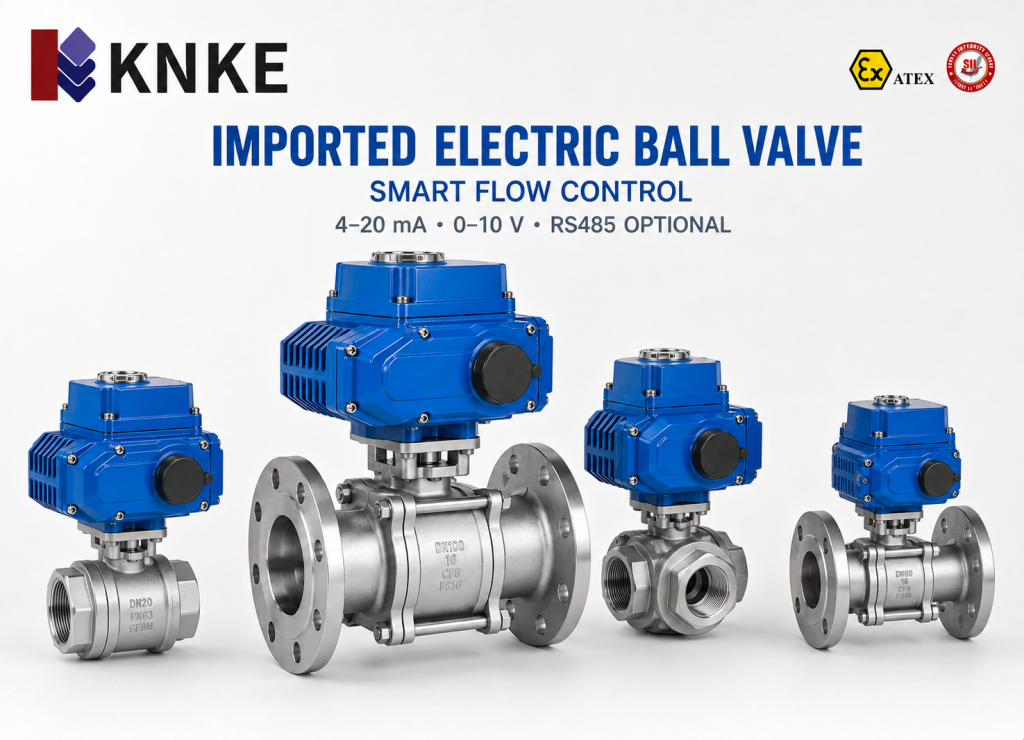
USA KNKE offers imported electric control ball valves for CDUs, heat exchangers, circulation pipes, and server rack branches. The valve works with an electric actuator. It changes the flow when the actuator receives a control signal.
AI servers create a large amount of heat. As rack power rises, air cooling may struggle with local hot spots. Liquid cooling transfers heat through water or a glycol solution. This method requires stable flow and pressure control.
Many liquid cooling systems use a supply and return temperature difference of about 5–10°C. Secondary-loop pressure often ranges from 0.3 to 1.0 MPa. The final values depend on rack load, pipe length, and heat exchanger size.
USA KNKE INDUSTRY INC has its headquarters in Colorado, USA. The company supplies valves, flowmeters, pumps, actuators, and fluid control solutions. KNKE Industry (Shenzhen) Co., Ltd. manages sales and service across the Asia-Pacific market.
Electric Control Ball Valve Parameters
AI data centers may use deionized water, softened water, or glycol solutions. Ethylene glycol and propylene glycol solutions often contain 20%–50% glycol by volume. A higher glycol level can increase fluid thickness. It can also increase pipe resistance.
Engineers should consider these changes during valve selection. Pipe size alone cannot define the correct valve size. The design flow and pressure difference also affect the required Kv value.
USA KNKE can provide imported electric control ball valves with stainless steel bodies. PTFE and reinforced PTFE are common seal options. The correct material depends on the coolant, additives, temperature, and pressure.
Common project options include:
- DN15 to DN100 sizes for many liquid cooling pipes;
- PN10, PN16, or other pressure ratings;
- 4–20 mA, 0–10 V, or on/off control signals;
- Valve position, fault, or communication feedback;
- AC24V, DC24V, or AC220V power supplies;
- Threaded or flanged connections.
These figures show common design ranges. They do not cover every product or project. Engineers should confirm all parameters before use.
Valve size can affect control quality. An oversized valve may stay almost closed during normal operation. Small changes may then cause unstable flow. An undersized valve may create high pressure loss. It may also raise pump energy use.
AI Data Center Application Case
A certain AI computing center planned a direct-to-chip liquid cooling area. Each rack had a design load of about 60–100 kW. Several racks connected to CDUs for heat exchange.
The secondary loop used an ethylene glycol solution. The glycol concentration was about 30%. The design set the supply temperature at about 30–35°C. It also set a temperature difference of 6–8°C.
The project considered an imported electric control ball valve for several locations. These included the CDU inlet, main circulation pipe, and high-load rack branches.
USA KNKE reviewed the design flow and pressure difference. One branch required a flow of about 8 m³/h. The planned pressure difference ranged from 30 to 50 kPa. The valve selection focused on the Kv value and normal opening range.
The design aimed to keep the valve away from very small openings. Long operation below 10% opening may reduce control stability. A suitable Kv value can help the valve work within a useful range.
The actuator would receive a 4–20 mA signal. It would send valve position data to the control platform. When server load increased, the system would open the valve further. When the load fell, the system would reduce branch flow.
The project remained under technical review. These figures explain the proposed design. They do not represent actual operating results.
Addressing Common Liquid Cooling Problems
A liquid cooling project includes valves, pipes, pumps, sensors, and control systems. Missing information can cause selection errors. It may also lead to signal conflicts or material problems.
USA KNKE supports projects in five main areas:
- Valve selection: The team checks the coolant, concentration, temperature, and flow. It also checks pressure, pipe size, voltage, and control signals.
- Product quality: The team reviews body material, seal material, actuator torque, and signal feedback. Technical files can support product checks.
- Delivery planning: Early confirmation can reduce later changes. Important details include voltage, connection size, signal type, and special functions.
- Document control: A complete model list can group the valve, actuator, and accessories. This makes technical and delivery lists easier to compare.
- Service support: Product codes and wiring diagrams can help locate faults. Staff can check the power supply, signal, actuator, and valve body.
Product size, quantity, transport, and site conditions can affect project time. The technical agreement should define the final schedule and service scope.
Electric Control Ball Valve Selection Guide
Engineers should first confirm the coolant and working conditions. They can then calculate the required Kv value. A suitable electric control ball valve should match both flow and pressure needs.
A large valve may work at a very small opening. This can make flow control difficult. A small valve may cause high pressure loss. It may also increase pump load.
When conditions allow, engineers can target a normal opening range of about 30%–80%. They should also check the valve flow curve.
The selection process should review:
- Coolant type, additives, and concentration;
- Minimum and maximum flow;
- System pressure and valve pressure difference;
- Control and feedback signals;
- Communication protocol;
- Fail-open, fail-closed, or stay-in-place action;
- Installation space and protection level;
- Access for inspection and maintenance.
A USA KNKE electric control ball valve can work with flowmeters and temperature sensors. It can also connect with pressure transmitters, pumps, PLCs, and building control systems. This setup can support flow control, temperature control, and branch balancing.
A liquid cooling project should not focus on one parameter alone. The valve size must match the required flow. The materials must suit the coolant. The actuator must also match the control system. Careful checks can reduce selection errors and support system control.or must match the control system. Careful checks can reduce selection errors and improve system coordination.