Vortex vs. Turbine Flowmeters: A Comprehensive Guide to Selection in Industrial Fluid Measurement
In industrial fluid measurement, vortex flowmeters and turbine flowmeters are two widely applied flow measurement devices. Despite sharing a similar-sounding name, they exhibit significant differences in their working principles, structural designs, and applicable scenarios. This article will thoroughly analyze their distinctions from the perspectives of technical principles, performance characteristics, and application scenarios to provide industrial users with a scientific reference for selection.
I. Working Principle: Application of Different Physical Effects
(A) Vortex Flowmeters: Precise Capture of the Kármán Vortex Street Effect
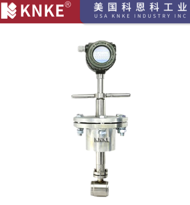
The core principle of a vortex flowmeter is based on the Kármán vortex street phenomenon in fluid mechanics. When fluid flows past a bluff body (such as a triangular prism or cylinder) installed in the pipeline, vortices are alternately generated on both sides of the body, forming a stable vortex street (i.e., Kármán vortex street). The frequency of vortex shedding is directly proportional to the fluid velocity. By capturing the frequency signal using sensors (e.g., piezoelectric, capacitive) installed on both sides of the bluff body, the fluid’s volumetric flow rate can be calculated.
Formula: f=St×dv (where f is the vortex frequency, St is the Strouhal number, v is the fluid velocity, and d is the width of the bluff body).
This principle dictates that vortex flowmeters do not require moving parts, achieving flow measurement purely through fluid oscillation phenomena, which provides strong stability and anti-interference capabilities.
(B) Turbine Flowmeters: Velocity Mapping through Impeller Rotation
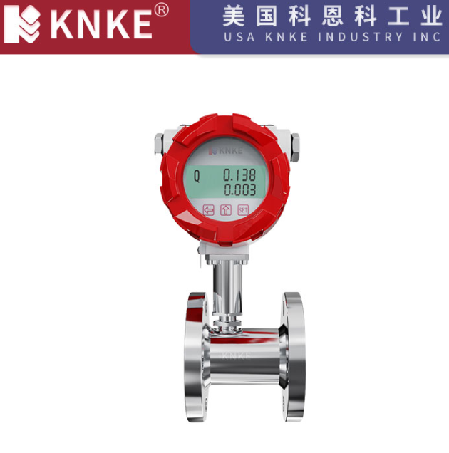
Turbine flowmeters belong to the category of velocity-type flowmeters. Their core component is a turbine impeller installed in the center of the pipeline. As fluid passes through, the impeller rotates due to the thrust of the fluid, and its rotational speed is directly proportional to the fluid’s average velocity. By detecting the impeller’s rotational frequency using a magnetic-electric or photoelectric sensor, and combining this with the impeller’s geometric parameters (e.g., number of blades, diameter), the fluid flow rate can be converted.
Formula: Q=K×f (where Q is the volumetric flow rate, f is the impeller rotational frequency, and K is the meter constant).
Because they rely on mechanical rotating parts, the measurement accuracy of turbine flowmeters is highly sensitive to fluid cleanliness, viscosity, and bearing life.
II. Core Performance Differences: Multi-Dimensional Comparative Analysis
(A) Measurement Medium Adaptability
- Vortex Flowmeters: Possess broad medium compatibility, capable of measuring gases, liquids (including water, oils), and steam, especially suitable for high-temperature steam (e.g., above 300℃) and low-viscosity fluids. Their measurement performance is virtually unaffected by fluid density, pressure, or temperature (though compensation may be needed for temperature). However, their measurement accuracy decreases for low flow rates (e.g., less than 0.5 m/s) and high-viscosity fluids (e.g., greater than 20 mPa·s).
- Turbine Flowmeters: Primarily designed for clean liquids (e.g., fuel, water, light oils). They perform poorly for gas measurement due to insufficient impeller drive force. When fluid viscosity is high (e.g., lubricating oil) or contains particulate impurities, the impeller’s rotational resistance increases, leading to bearing wear and affecting measurement accuracy and equipment lifespan.
(B) Structural Design and Maintenance Costs
- Vortex Flowmeters: Have no moving parts, resulting in a simple structure (only a vortex-shedding body and sensors). They require virtually no routine maintenance after installation. They exhibit strong vibration resistance but demand high requirements for pipeline vibration and flow field uniformity, necessitating sufficiently long straight pipe sections (10D upstream, 5D downstream, where D is the pipe diameter).
- Turbine Flowmeters: Contain mechanical components such as an impeller, bearings, and a drive shaft. Long-term operation may lead to drift in the meter constant due to wear, requiring regular disassembly for cleaning and bearing replacement (especially in fluids containing impurities). Their structure is relatively complex, but their smaller size makes them suitable for compact installations.
(C) Accuracy and Turndown Ratio
- Accuracy: Both can achieve high accuracy. Under ideal conditions, vortex flowmeters can achieve an accuracy of ±1% R (1% of full scale) with strong stability, being less affected by fluctuations in medium parameters. Turbine flowmeter accuracy is typically ±0.5% R to ±1% R, but accuracy can easily decline with viscosity changes or bearing wear.
- Turndown Ratio: Vortex flowmeters offer a wider turndown ratio (typically 10:1 to 20:1), accommodating large variations in flow velocity. Turbine flowmeters have a relatively narrower turndown ratio (usually 5:1 to 10:1), making them more suitable for stable flow rate scenarios.
(D) Pressure Loss and Energy Consumption
Pressure loss in vortex flowmeters primarily results from the obstruction of the fluid by the vortex-shedding body, with a relatively low pressure loss coefficient (ΔP) (approximately 0.1 to 0.3 MPa). Turbine flowmeters experience slightly higher pressure loss (approximately 0.2 to 0.5 MPa) because the impeller rotation must overcome mechanical resistance, which needs to be considered for energy consumption in high-pressure pipeline systems.
III. Application Scenarios: Key Basis for Selection
(A) Typical Scenarios for Vortex Flowmeters
- Diverse Medium Scenarios: Gas (e.g., hydrogen, nitrogen) and steam (superheated steam, saturated steam) metering in the chemical industry; steam flow monitoring in heating systems; exhaust gas emission measurement in environmental protection.
- Large Pipe Diameter and High Flow Rate: Suitable for pipelines from DN50 to DN3000, with significant advantages in large flow scenarios such as urban water supply and gas distribution.
- Harsh Operating Conditions: High-temperature resistance (e.g., 350℃), corrosion resistance (requires special material for the shedding body), suitable for high-temperature and high-pressure environments in metallurgy and power industries.
(B) Typical Scenarios for Turbine Flowmeters
- Clean Liquid Metering: Finished oil (gasoline, diesel) metering in petroleum refining; lubricating oil flow monitoring in hydraulic systems; pure water metering in the pharmaceutical industry.
- Medium Pipe Diameter and Stable Flow Rate: Commonly used pipe diameters from DN15 to DN500, suitable for small to medium-scale pipelines, such as fuel dispensers at gas stations and industrial circulating water systems.
- High Precision Requirements: In scenarios with stable viscosity (e.g., low-viscosity liquids) and few impurities, they can leverage their high-accuracy advantage, such as laboratory fluid calibration and fine chemical batching.
IV. Selection Decision: Five-Element Evaluation Method
- Medium Characteristics: Prioritize vortex flowmeters for gases, steam, and multiphase flows; turbine flowmeters for clean, low-viscosity liquids.
- Pipe Diameter and Flow Rate: Choose vortex flowmeters for large pipe diameters (DN ≥ 200) and high flow rates (> 5 m/s); turbine flowmeters for small to medium pipe diameters (DN ≤ 300) and medium to low flow rates (0.5 to 10 m/s).
- Accuracy Requirements: For long-term stable measurement, choose vortex flowmeters (resistant to parameter fluctuations); for short-term high-precision calibration, choose turbine flowmeters (requires regular calibration).
- Maintenance Costs: For unmanned or high-maintenance difficulty scenarios, choose vortex flowmeters (maintenance-free); turbine flowmeters can be chosen for scenarios allowing regular maintenance.
- Environmental Conditions: Choose vortex flowmeters for high-temperature, high-pressure, and strong vibration environments; choose turbine flowmeters for low-temperature, clean environments.
V. Conclusion: Complementary Technologies, Scenario-Driven Selection
While both vortex and turbine flowmeters fall under the category of velocity-type measurements, their differing principles lead to complementary application boundaries. The former, with its no-moving-parts design and wide medium adaptability, serves as a “versatile player” in many industrial scenarios. The latter, with its high accuracy and compact structure, holds an advantage in clean liquid measurement.
When making a selection, users must consider multi-dimensional factors such as medium type, operating conditions, and maintenance capability. If necessary, on-site testing can be conducted to verify instrument performance, ensuring the accuracy and reliability of flow measurement. As industrial automation levels advance, the intelligent upgrading of both types of flowmeters (e.g., integration of IoT modules, multi-parameter compensation) will further expand their application scope, providing crucial data support for the digital transformation of process industries.