The Difference Between a Piston Valve and a Gate Valve
In industrial piping systems, valves are critical components for controlling fluid flow and shut-off, with their selection directly impacting system safety, stability, and economy. Plunger valves and globe valves both belong to the linear motion valve family and are widely used due to their simple structure and ease of operation. However, there are significant differences in their technical performance, structural design, and applicable scenarios. This article, referencing the technical parameters of KNKE valves from the United States, provides a professional analysis of the core distinctions between the two.
1. Core Technical Parameter Comparison
(I) Pressure Resistance: A Significant Difference in Pressure Ratings
The design pressure limit for a plunger valve is typically 4 MPa, making it suitable for low-to-medium pressure applications. Its sealing structure makes the seal rings susceptible to deformation from stress concentration in high-pressure environments, which can lead to sealing failure.
Globe valves, on the other hand, have a much greater high-pressure tolerance, with maximum working pressures reaching up to 75 MPa (approx. 4500 LB). By optimizing the sealing surface angle between the disc and the seat (e.g., a 60° cone design) and using high-strength body materials (such as forged steel or stainless steel), they can withstand severe high-differential pressure conditions, such as high-pressure fluid control in petrochemical pipelines.
2. Sealing Principle: Different Approaches to Contact Sealing
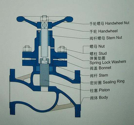
Plunger valves use a “plunger-seal ring” flexible sealing structure, consisting of a stainless steel plunger, upper and lower elastic sealing rings (made of PTFE or rubber), and a metal spacer. During operation, the plunger moves linearly within the seal rings. The sealing contact area is 1.5 to 2 times the valve’s nominal diameter, and contact surface wear is minimal during movement. In the closed position, the plunger is inserted into the lower seal ring to form a shut-off. When open, the plunger remains inside the upper seal ring, achieving “zero leakage” isolation (as shown in Figure 1).
Globe valves are a forced sealing type of valve that relies on rigid contact sealing between the disc and the seat. When the medium enters from below the disc, closing the valve requires overcoming the thrust generated by the medium’s pressure (which can be 2-3 times the opening force), which can easily lead to stem bending or sealing surface wear. To improve sealing performance, high-end products (such as KNKE bellows-sealed globe valves) use a “disc seal + bellows” dual-sealing structure, which prevents packing leakage and extends the stem’s lifespan.
3. Structural Design and Operational Characteristics
(I) Component Composition: Function-Oriented Differentiated Design
The core components of a plunger valve include the body, bonnet, plunger, cage, and seal rings. The cage acts as a guide for the plunger’s movement, and its machining precision directly affects the smoothness of the valve’s operation. The choice of seal ring material (e.g., a metal bellows seal for high-temperature service) determines the valve’s temperature range (typically -20℃ to 350℃).
A globe valve mainly consists of the stem, body, disc, gasket, and handwheel. The disc sealing surface can be designed as flat (suitable for water) or conical (suitable for steam), and with a streamlined body flow path, its flow resistance coefficient is only 0.2-0.3, similar to a straight pipe section of the same diameter, significantly reducing fluid pressure drop.
(II) Operational Performance: A Trade-off Between Effort and Control Precision
The advantage of a plunger valve lies in its low operating torque. The friction between the plunger and the seal rings is sliding friction, and the sealing surface wear rate is low (wear <0.05mm after 1,000 cycles). This makes it particularly suitable for applications requiring frequent operation. However, due to the longer plunger travel (typically 1.2 times the nominal diameter), its flow regulation precision is lower than that of a globe valve.
A globe valve has a shorter disc travel (approx. 0.8 times the nominal diameter), allowing for precise flow control (regulation precision up to ±5%) through fine adjustment of the stem threads. However, it requires greater operating force to close, and sizes DN100 and above often need a gearbox or electric actuator.
4. Application Scenario Analysis
(I) Plunger Valves: The Preferred Choice for Saturated Steam Systems
In saturated steam applications like heating networks and food processing, the long lifespan and low-leakage characteristics of plunger valves stand out. For instance, a KNKE plunger valve used in a power plant’s low-pressure steam pipeline (1.6 MPa, 180°C) operated continuously for 5 years without sealing failure, extending the replacement cycle by 3 times compared to traditional globe valves. Its sealing structure prevents impurities in the steam from eroding the sealing surface, making it suitable for media containing particles.
(II) Globe Valves: Versatile All-Rounders for Multiple Conditions
The broad applicability of globe valves stems from their high pressure and temperature resistance (up to 600℃) and precise control capabilities. In chemical pipelines (e.g., for concentrated hydrochloric acid or liquid ammonia), selecting a corrosion-resistant Hastelloy body and hardened alloy sealing surfaces can meet the control requirements for highly corrosive media. In boiler superheated steam pipelines (32 MPa, 540℃), the KNKE bellows-sealed globe valve’s dual-sealing design solves leakage problems caused by packing aging at high temperatures.
5. Valve Selection Decision-Making Guide
- Pressure Rating: For low-pressure systems (≤ 4 MPa), prioritize plunger valves. For medium-to-high-pressure systems (> 4 MPa), a globe valve must be used.
- Medium Characteristics: For media containing particles or prone to fouling, choose a plunger valve (with a self-cleaning sealing structure). For clean fluids or applications requiring precise regulation, choose a globe valve.
- Operating Frequency: For frequently operated scenarios (e.g., >10 times a day), choose a plunger valve (effort-saving and wear-resistant). For intermittent operation, a globe valve is an option.
- Temperature Range: For low temperatures (< -50℃) or ultra-high temperatures (> 450℃), consider using a globe valve made of special alloy materials.
Although plunger valves and globe valves are both linear motion valves, their design philosophies reflect different priorities: “sealing first” versus “control first.” In engineering practice, valve selection must be a comprehensive decision based on media parameters (pressure, temperature, corrosiveness), operational requirements (frequency of operation, regulation precision), and system safety needs. With advancements in materials and sealing technologies, the performance boundaries of both valve types are constantly expanding (e.g., the development of high-pressure plunger valves and low-torque globe valves), providing more precise solutions for industrial fluid control.