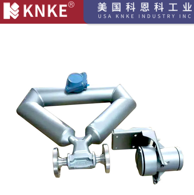
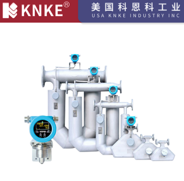
Mass Flow Meter Installation Requirements: Key to Accurate Measurement
In industrial processes, mass flow meters are critical devices for precise fluid mass flow measurement. Their installation quality directly impacts measurement accuracy, equipment lifespan, and system stability. Proper installation is the foundation for optimizing performance. This article systematically outlines key installation considerations for mass flow meters, covering location selection, pipeline layout, and environmental adaptation based on engineering practices and technical standards.
1. Installation Location: Foundation for Stable Measurement
1.1 Choose Stable Flow Zones
Mass flow meters must be installed on straight pipe sections, away from elbows, valves, branch pipes, and pump outlets—areas prone to flow disturbances like eddies or turbulence. These locations can cause uneven flow distribution and measurement errors. For optimal performance:
- Liquid media: Maintain at least 10D straight pipe length upstream and 5D downstream (D = pipe diameter).
- Gas media: Adjust straight pipe requirements based on flow velocity and pipe roughness (refer to the manufacturer’s manual for specific parameters).
Stable flow ensures the fluid reaches a fully developed state before entering the meter, minimizing measurement deviations.
1.2 Avoid Vibration and Mechanical Interference
Vibration is a major threat to measurement accuracy. Install meters away from vibration sources like compressors or motors. If pipeline vibration is unavoidable (e.g., reciprocating pump outlets), use flexible hoses or vibration-damping supports 200–300mm upstream/downstream to isolate mechanical disturbances. For Coriolis mass flow meters, ensure rigid connections to prevent resonance that could disrupt signal acquisition.
1.3 Reserve Maintenance Space
Allow sufficient access for calibration, inspection, and troubleshooting:
- Maintain at least 1.2m of clearance on both sides and 1.5m of overhead space for easy component replacement or calibration device access.
- For installations in elevated or confined spaces, design maintenance platforms or supports in advance to avoid operational restrictions.
2. Pipeline Installation: Critical for Precision
2.1 Coaxial Alignment and Sealing
Ensure strict coaxial alignment between the meter and upstream/downstream pipelines, with a flange parallelism error ≤1mm to prevent flow deflection. Use specialized gaskets (e.g., spiral-wound metal gaskets, PTFE gaskets) that do not protrude into the pipeline to avoid sensor damage or flow dead zones. For large-diameter pipes (DN≥300mm), use alignment fixtures to reduce human error.
2.2 Flow Direction and Orientation
Follow the flow direction indicated on the meter (e.g., arrow marks) to avoid reverse flow, which can render measurements invalid.
- Liquids: Install in vertical upward-flow sections or fully filled horizontal pipes to prevent partial flow.
- Gases: Avoid low-point installations to prevent condensate accumulation.
Proper orientation ensures consistent fluid contact with sensors and stable signal output.
2.3 Bypass Pipeline and Valve Configuration
In critical processes, install isolation valves and bypass pipelines upstream/downstream of the meter:
- Isolation valves facilitate maintenance without system shutdown.
- Bypass pipelines maintain continuous operation during meter servicing, reducing downtime losses.
Ensure bypass diameter matches the main pipeline and valves are easily operable.
3. Environmental Adaptation: Addressing Complex Conditions
3.1 Electromagnetic and Thermal Interference Protection
Shield meters from strong electromagnetic sources (inverters, transformers, high-voltage cables) by routing signal cables in shielded conduits, keeping at least 300mm away from power cables. For high-temperature environments (media temp >150°C or ambient temp >60°C), use thermal insulation or high-temperature models and avoid direct sunlight on the display. In low-temperature settings, apply trace heating to prevent media freezing or sensor condensation.
3.2 Corrosion and Erosion Protection
Select corrosion-resistant materials (e.g., PTFE-lined, Hastelloy electrodes) for aggressive media (acids, alkalis). Clean pipelines before installation to remove residual corrosives. For particulate-laden fluids (slurries, sandy gases), install upstream filters (mesh accuracy ≤50μm) and schedule regular cleaning to prevent sensor wear or pipe blockage.
3.3 Special Scenario Installations
- Vertical pipelines: Suitable for upward liquid flow or downward gas flow; ensure full liquid filling or no condensate buildup.
- Small-diameter pipes (DN≤50mm): Strengthen pipeline rigidity to avoid stress concentration; use welded short pipes with heat dissipation during installation.
- Explosion-proof areas: Choose explosion-rated models (e.g., Ex d IIC T6), seal junction boxes, and comply with explosion-proof cable entry requirements.
4. Installation Procedures and Best Practices
4.1 Pre-Installation Preparation
Verify meter specifications (model, diameter, flow direction) against design documents. Inspect for physical damage and ensure all accessories (flanges, bolts, gaskets) are included. Pre-clean pipelines to remove debris (weld slag, rust) and consider acid cleaning for critical applications.
4.2 Lifting and Fixing
Use specialized lifting tools (nylon slings) to avoid deforming the measurement tube. Tighten flange bolts symmetrically in 2–3 stages to meet torque requirements (e.g., ~120N·m for DN100 flanges), preventing sealing failure due to uneven stress.
4.3 Debugging and Calibration
After installation, power on the meter to check sensor signals and zero drift (typically ≤±0.1% of full scale). For trade measurement purposes, conduct on-site calibration by an accredited metrology institution and record installation parameters for future reference.
Mass flow meter installation is a systematic task requiring integration of fluid dynamics, equipment specifications, and site conditions. Every detail—from location selection to environmental adaptation—matters for minimizing errors and ensuring reliability. Follow manufacturer manuals and industry standards (e.g., GB/T 2624 for differential pressure flow measurement) to develop tailored installation plans. By prioritizing precision in every step, you can guarantee long-term stable operation, providing a solid foundation for accurate industrial measurement and process control.