Key Components of Centrifugal Pumps: Impeller, Casing & Sealing Explained
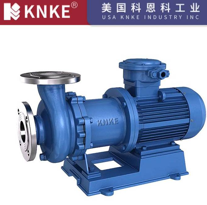
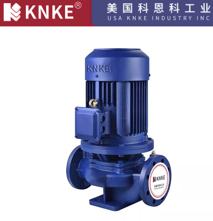
In the realm of industrial fluid transportation, centrifugal pumps stand out as core equipment in sectors such as petrochemicals, water conservancy, power generation, and wastewater treatment, primarily because of their compact design, high efficiency, and versatile applications. As a professional provider of fluid handling solutions, KNKE is committed to enhancing pump performance and reliability through optimized design of key components. This article delves into the main components of centrifugal pumps and their critical roles in ensuring efficient operation, thereby showcasing KNKE’s technical expertise in pump engineering.
1. The Heart of Energy Conversion: Impeller – The Dynamic Core of Centrifugal Pumps
The impeller is the central component where mechanical energy is converted into fluid kinetic energy, and its design precision directly impacts pump efficiency. At KNKE, we craft centrifugal pump impellers from high-strength alloy materials (such as stainless steel and duplex steel) using precision casting, which ensures blade profiles align perfectly with fluid dynamics.
- Structure & Design: Specifically, these impellers comprise front/back shrouds, vanes, and a hub. We custom-engineer them based on medium properties (viscosity, corrosivity), offering common types like closed, semi-open, and open impellers.
- Functionality: By generating centrifugal force through high-speed rotation, impellers transfer mechanical energy to liquids, thereby increasing both kinetic and static pressure energy. To achieve this, KNKE utilizes CFD (Computational Fluid Dynamics) simulation to minimize hydraulic losses, thus achieving industry-leading impeller efficiency.
- Application Advantages: For instance, when dealing with diverse operating conditions (high head, large flow), KNKE offers multi-type impeller solutions. In particular, multi-stage pump impellers feature geometrically similar diameters, which helps ensure uniform energy distribution and reduce axial force effects.
2. Fluid Management Hubs: Pump Casing & Suction Chamber – Key Structures for Efficient Flow Guidance
1. Suction Chamber: The Pre-Flow Channel for Smooth Liquid Intake
Located at the front of the impeller inlet, the suction chamber plays a crucial role in directing liquids uniformly into the impeller, thereby minimizing flow resistance and cavitation risks. At KNKE, we employ tapered bell-mouth suction chambers with polished internal surfaces (surface roughness ≤ Ra1.6), a design that ensures low-turbulence fluid entry. Moreover, for particle-laden media, we add inlet guide vanes to prevent debris accumulation.
2. Pump Casing (Volute/Discharge Chamber): The Energy Converter from Kinetic to Static Energy
The pump casing not only contains the fluid but also converts high-speed kinetic energy from the impeller into static pressure energy. To achieve this efficiently, KNKE utilizes two main casing structures:
- First, the spiral volute, ideal for single-stage pumps, features a gradually expanding cross-section that converts 60%-70% of kinetic energy into static pressure. Additionally, pressure-balanced outlet flanges help reduce pipeline vibrations.
- Second, the diffuser-type casing, used in multi-stage pumps, relies on guide vanes to direct fluid flow, thereby increasing pressure step-by-step. Compared to traditional volutes, this design reduces radial loads by 30%, thus extending bearing life.
3. Sealing & Stability Assurance: Shaft Seals, Wear Rings & Balance Devices
1. Shaft Sealing Devices: The Leakage-Proof Barrier
To prevent fluid leakage or air ingress at the shaft-housing interface, KNKE offers multiple sealing solutions. For example, mechanical seals feature silicon carbide/tungsten carbide friction pairs with spring-loaded compensation, a design that suits high-temperature, high-pressure, and corrosive media while controlling leakage below 5ml/h. On the other hand, packing seals use high-elasticity graphite packing with water-sealed cooling rings, making them ideal for particle-containing media with low maintenance costs. Importantly, all seals undergo 72-hour pressure testing to ensure stability in -40°C~350°C environments.
2. Wear Rings (Sealing Rings): The Energy-Saving Key for Reduced Backflow
Installed between the impeller inlet and pump casing, wear rings serve to control clearances, thereby minimizing liquid recirculation from high-pressure to low-pressure zones. At KNKE, we design replaceable wear rings (hardness ≥ HRC55) with precision grinding, a process that maintains radial clearances of 0.05-0.15mm (model-dependent). As a result, this reduces volumetric loss by 20%, significantly enhancing pump efficiency.
3. Balance Devices: The Dynamic Regulators for Axial Thrust
In multi-stage pumps, pressure differences across impellers generate axial forces that can wear bearings. To address this, KNKE’s standard automatic balance discs neutralize over 95% of axial thrust via pressure feedback. Similarly, for single-stage pumps, we use back vanes on impellers to reduce both axial force and back pressure, thereby extending bearing life by 30%.
4. Structural Support & Power Transmission: Shaft & Pump Body
1. Shaft: The High-Strength Power Bridge
As the connection between the motor and impeller, the shaft must withstand combined loads of torque, bending, and axial force. At KNKE, we forge shafts from 42CrMo alloy steel, a material that achieves a yield strength ≥ 930MPa after quenching and tempering. Additionally, precision dynamic balancing (G2.5 grade) ensures vibration ≤ 2.5mm/s at 3000rpm and noise < 85dB.
2. Pump Body: The Robust Foundation for Durability
KNKE prioritizes both strength and maintainability in pump body design. For horizontal pumps, we use horizontal split casings, a feature that allows maintenance without pipeline disassembly, thereby improving service efficiency by 50%. Meanwhile, vertical pumps feature double-layer casings: an outer carbon steel layer for pressure resistance and an inner rubber/PTFE lining for corrosion resistance, making them suitable for strong acid/alkali media. Importantly, all pump bodies pass 1.5x design pressure hydrostatic testing, ensuring over 10 years of service life.
KNKE’s Technological Innovation: Synergistic Optimization for Exceptional Performance
As a fluid handling solutions expert, KNKE focuses on system-wide optimization rather than individual components. For example, our data-driven models optimize impeller outlet angles and volute base circles, a process that boosts pump efficiency by 5%-8%. Additionally, we integrate smart sensors into seal chambers to provide real-time leakage and temperature feedback, thereby enabling predictive maintenance. In harsh environments, we apply HVOF-sprayed tungsten carbide coatings to impellers, which enhance wear resistance by 400%.
From core flow components to auxiliary sealing structures, every part of a centrifugal pump is designed for efficiency, stability, and durability. At KNKE, we leverage detailed component-level R&D to deliver customized solutions, thereby catering to global industrial needs. Whether for standard operations or harsh environments, KNKE centrifugal pumps stand as a reliable backbone for industrial production.