Description
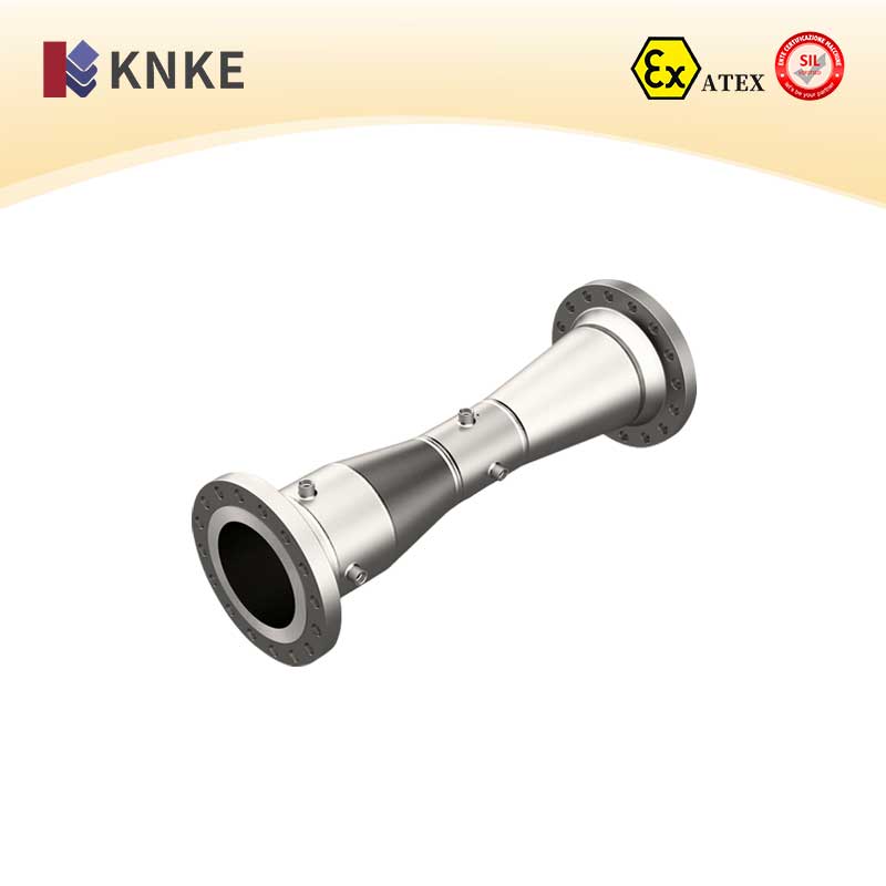
1. Overview of the KNKE Venturi Flow Meter
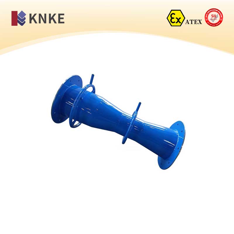
The KNKE Venturi flow meter is an efficient device for measuring fluid flow in pipelines. It operates by creating a restriction in the pipe, causing the fluid velocity to increase and pressure to drop. This generates a pressure differential, which is proportional to the square root of the flow rate.
Compared to other flow meters, the Venturi meter is highly accurate and reliable. It performs well in various industries, including oil, chemical, power, and metallurgy. Its design ensures low energy consumption, high durability, and resistance to clogging. It’s suitable for a wide range of fluids and environments, from normal temperature and pressure to extreme conditions.
2. Measurement Principle of the KNKE Venturi Flow Meter
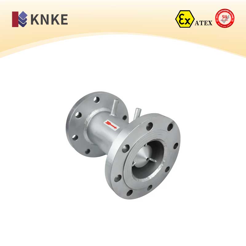
The Venturi flow meter works based on the principle of differential pressure measurement. It uses Bernoulli’s equation and the continuity equation. As fluid flows through the constriction, it accelerates, creating a pressure differential. This differential is directly related to the flow rate.
The design of the Venturi tube helps avoid issues like cavitation and clogging, which are common in other flow meters. This ensures stable and accurate flow measurement, even in challenging industrial environments. The meter is especially effective for gases with impurities, such as blast furnace gas and flue gas.
3. Key Features of the KNKE Venturi Flow Meter
| Feature | Description |
|---|---|
| Low Energy Consumption | It has minimal resistance (around 150Pa), reducing energy use. |
| High Accuracy & Wide Range | It offers a large differential pressure, ensuring high accuracy across various applications. |
| Stability | The meter has a smooth differential pressure characteristic, ensuring stable performance. |
| Wide Application | Suitable for clean gases, flue gases, blast furnace gas, and fluids with impurities. |
| Ease of Installation & Maintenance | The flow meter is easy to install and requires little maintenance. |
| Reduced Pipe Requirements | It requires shorter upstream and downstream pipe lengths compared to traditional devices. |
| Integrated Temperature and Pressure Compensation | The meter adjusts for temperature and pressure variations automatically. |
4. Technical Specifications of the KNKE Venturi Flow Meter
| Parameter | Specification |
|---|---|
| Nominal Diameter | 50mm ≤ DN ≤ 1200mm |
| Throttling Orifice Ratio (β) | 0.3 ≤ β ≤ 0.75 |
| Differential Pressure | 0~1.0, 1.6, 2.5, 4.0, 6.3, 10, 16KPa |
| Repeatability Error | ±0.5% |
| Accuracy Grade | 0.5, 1, 1.5, 2 |
| Operating Temperature | Below 400°C (Above 400°C requires special order) |
| Operating Pressure | PN ≤ 6.4MPa |
| Sensor Connection Size | G3/4″, M20×1.5 or 1/2NPT |
| Stability | ±10Pa |
| Reynolds Number Range | 2×10⁵ ≤ ReD ≤ 2×10⁶ |
5. Application Areas of the KNKE Venturi Flow Meter
The Venturi flow meter is used across various industries for measuring different fluids:
- Oil Industry: For measuring blast furnace gas, cooling air, and combustion air.
- Power Industry: Suitable for measuring primary and secondary air, and coal wind in power plants.
- Chemical Industry: Ideal for measuring enriched air, gases, and other complex media.
- Metallurgy Industry: Used for measuring gases like blast furnace gas and flue gas.
It ensures precision and adaptability for various industrial applications.
6. Installation and Maintenance of the KNKE Venturi Flow Meter
For proper installation, ensure the length of the upstream and downstream pipe sections meets the required specifications. The upstream pipe should be at least five times the pipe diameter, and the downstream pipe should be at least twice the diameter. Install the flow meter in a way that minimizes interference, and ensure it remains level for optimal performance.
This flow meter is easy to install, and its simple design requires minimal maintenance, ensuring long-term stability.
7. Pre-Operation Checks of the KNKE Venturi Flow Meter
Before starting the flow meter, follow these steps:
- Verify the correct installation of all transmitters (differential pressure, pressure, and temperature).
- Ensure all connections are tight and leak-free.
- Confirm proper wiring of secondary instruments and check the power supply connections.
- Once everything is checked, connect the secondary instruments to the power supply and begin operation.